Fast Robots: ECE 4960 Lab 1
In lab 1, we will setup the Artemis board and the software environment for the following projects. I followed the instructions to download Arduino IDE on my Mac with the version 10.13.6. However, once the Arduino was installed, I opened the software preference and added “https://raw.githubusercontent.com/sparkfun/Arduino_Boards/master/IDE_Board_Manager/package_sparkfun_index.json” in the additional board manager URL box. Then, I downloaded the Artemis board documents by searching in boards manager. After the board installation was complete, I hooked the Artemis board up to my computer. The complete set up is shown in Figure 1.
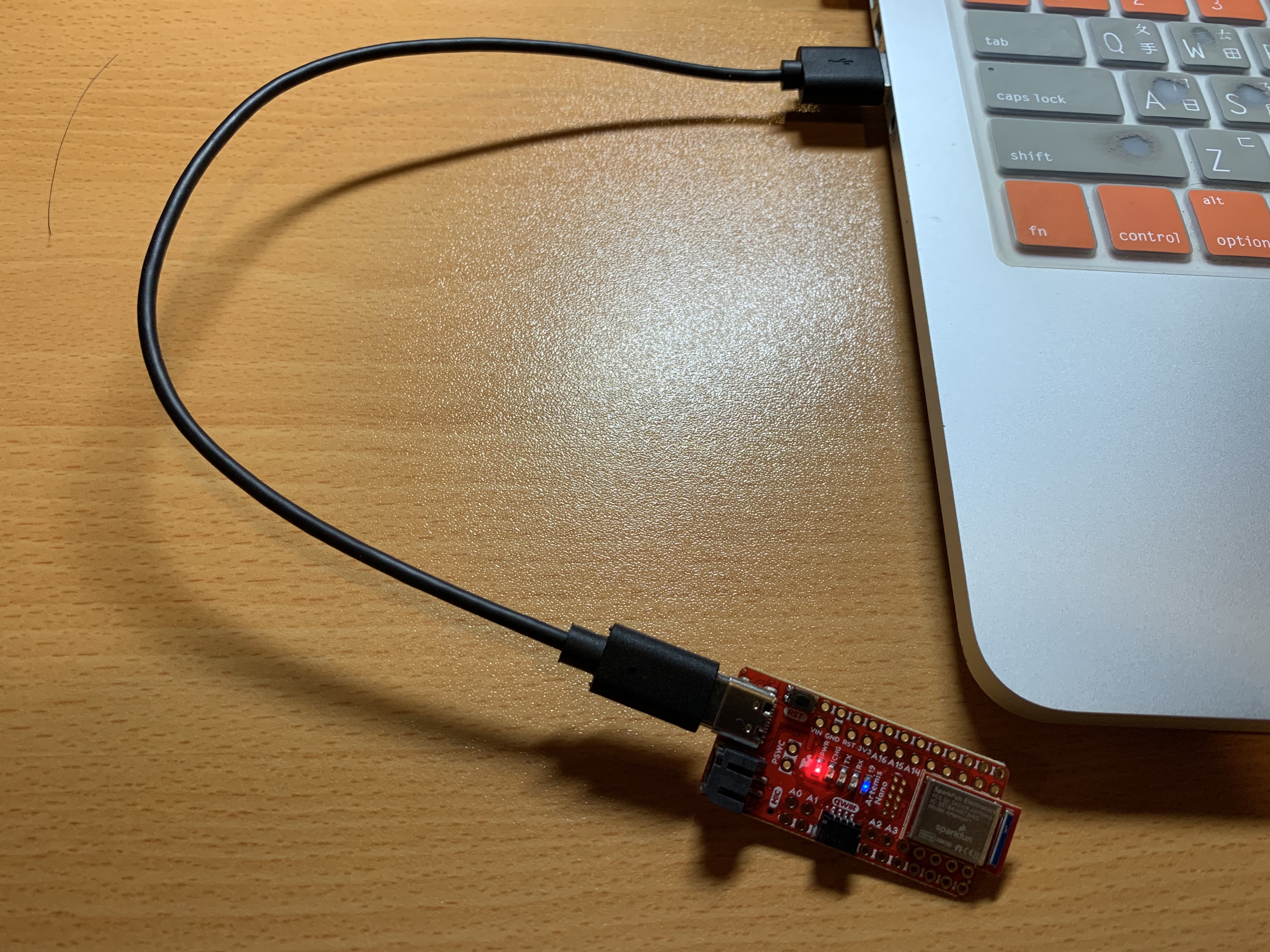
Figure 1. Artemis board setup.
However, the system showed an error message “Artemis SVL Bootloader /DEV/CU.USBMODEM1411 not found but we detected the following serial ports: n/a”. Therefore, I tried to debug the error by searching the solution online and asking TA in Campuswire. I found the answer that there was no serial port support on my computer, so I cannot use the USB-C. So, I followed the same process and the Artemis board worked on my Windows system. Next, I followed the instructions in “Example: Blink it Up” to test the LED feature on the board. I used two different delay values which show in Figure 2 to show the relationship between the blink frequency and the delay values.
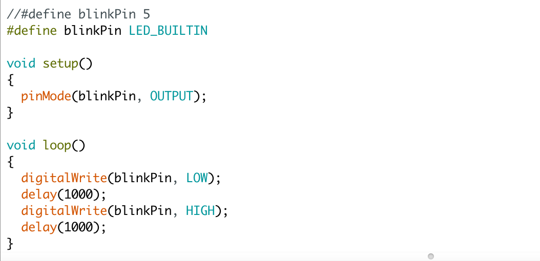
Figure 2. Blink code.
In Video 1, the delay value is 1000 and the value is 500 in Video 2, so we can see the LED blinks more frequently when the delay value is smaller.
Video 1: LED Blink with 1000 ms delay.
Video 2: LED Blink with 500 ms delay.
Next, we tested the serial port by running the serial example (Example2_serial) that was provided in the Artemis example libraries. In the video, when we input “a”, the port will return the message of how many cheeses to dispense in the system. When we input “x”, the system will quit the program.
Video 3: Serial port example.
Later, we tested the analog read features by running the Example4_analogRead program. The program will detect the chip’s temperature and returns the value in Celsius. We can see that when we were blowing on the chip, the temperature increased in the video.
Video 4: Analog read example.
Last, we tested the pulse density microphone on the board by running the Example1_MircophoneOutput. The program will find the frequency bin with the largest magnitude. At first, the serial monitor returns random values in the serial monitor while the program was running, which shows in Figure 3.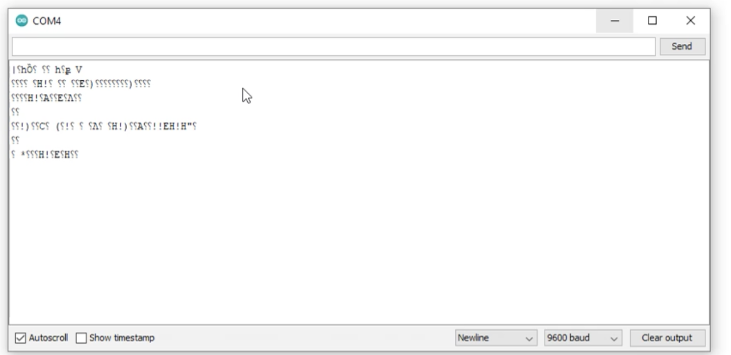
Figure 3. Random value in the serial monitor.
I asked the TA about the situation, and I got the answer that the baud rate has to match the value in the serial setup. Once debugging, the serial number could show the proper value of the frequency, which shows in the following video.Video 5: Microphone example.
After finishing the board testing, we hooked up the battery to the Artemis board, and the yellow LED was light-up, which shows in Figure 4.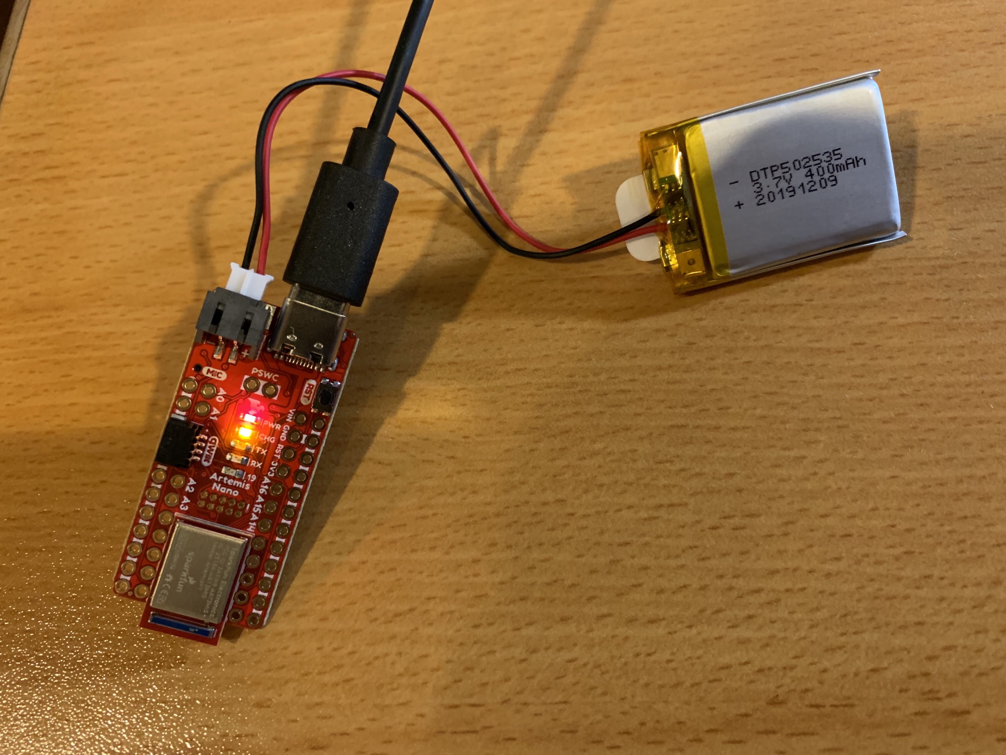
Figure 4. Artemis board with the battery (Li-Ion, 3.7V, 400 mAh).
In the lab exercise, we need to make make the program turn on the LED when people whistle and off otherwise. I realized that the frequency value of the whistle sound will almost larger than 1000, so I made a slight change in the audio example by adding an if statement to set up the condition. When the frequency value is larger than 1000, the LED will turn on. The code is shown in Figure 5 and the demonstration is shown in the following video.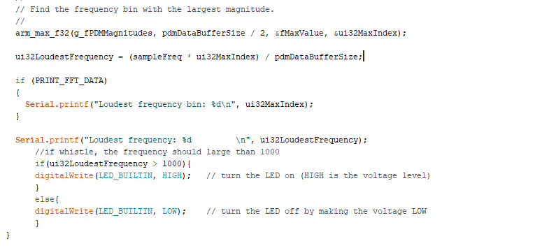
Figure 5. The code that is modified in the Example1_MircophoneOutput.
Video 6: Exercise with PC connected.
Video 7: Exercise without PC connected.