Fast Robots: ECE 4960 Lab 4
Introduction
In lab 4, we are going to assemble the Sparkfun Qwiic motor driver with the Artemis board to control two motors of the RC car. In the first section, we will write an Arduino program to open-loop control the RC car physically, and in the second section, we will write a simple python script with the Jupyter notebook to control the virtual robot in the simulator.In this section, we will re-assemble our RC car. We will need a small screwdriver to unscrew the upper platform and the bottom platform of the RC car. We could see that there are a PCB board, a power cable, and two DC motors in the upper side container, which is shown in Figure 1. The bottom side of the RC car has a battery connector.
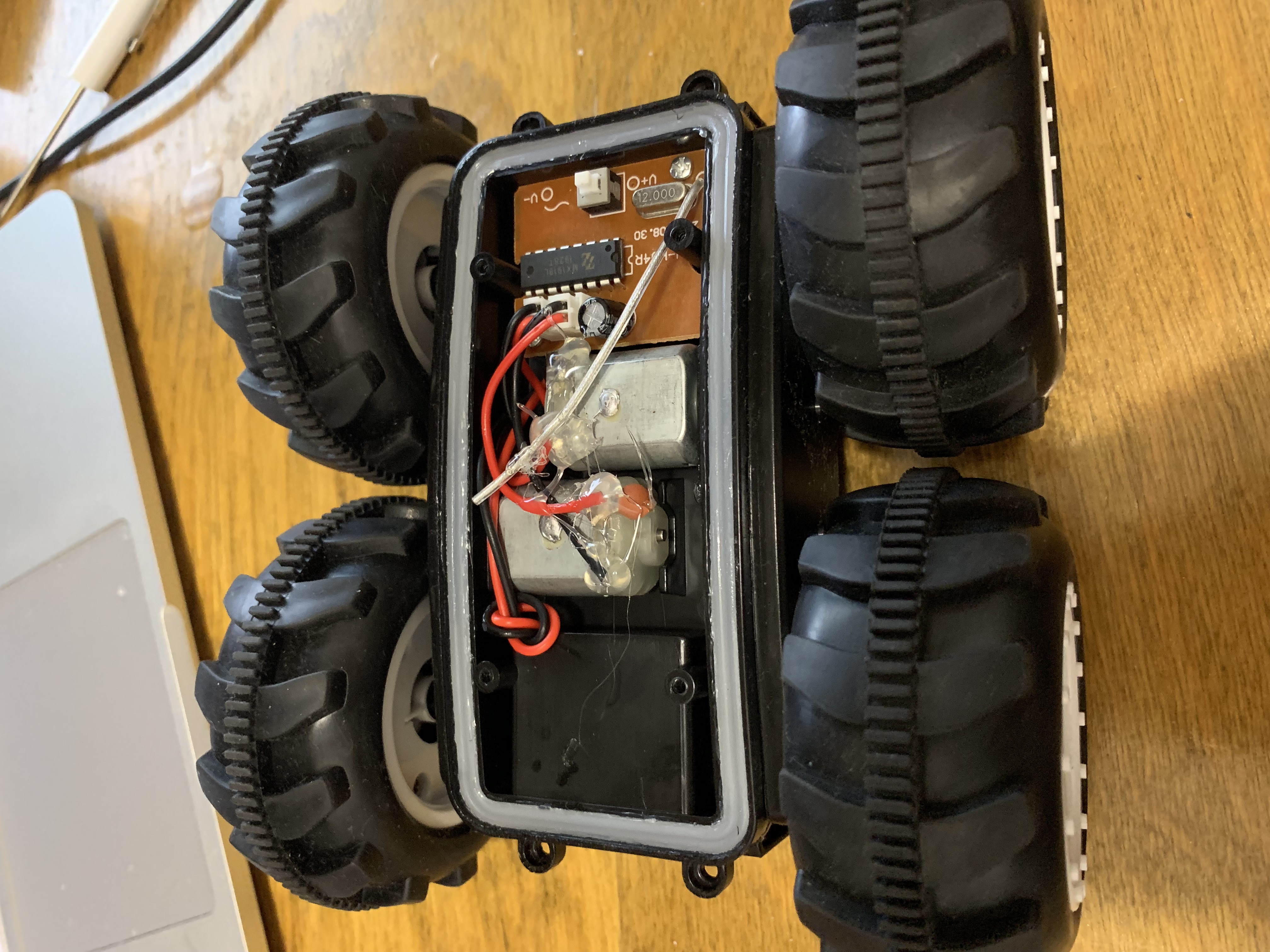
Figure 1: The overview of the robot’s internal structure.
Motor Drive Assembled
We will unsolder the power cable from the PCB board and connect it to the Serially Controlled Motor Driver (SCMD). Besides, we will have to cut both motors’ wires and hook them up to the SCMD. Then, we will connect the SCMD board with the Artemis board using a Qwiic connector and connect the battery to the car’s power socket. The complete assemble is shown in Figure 2.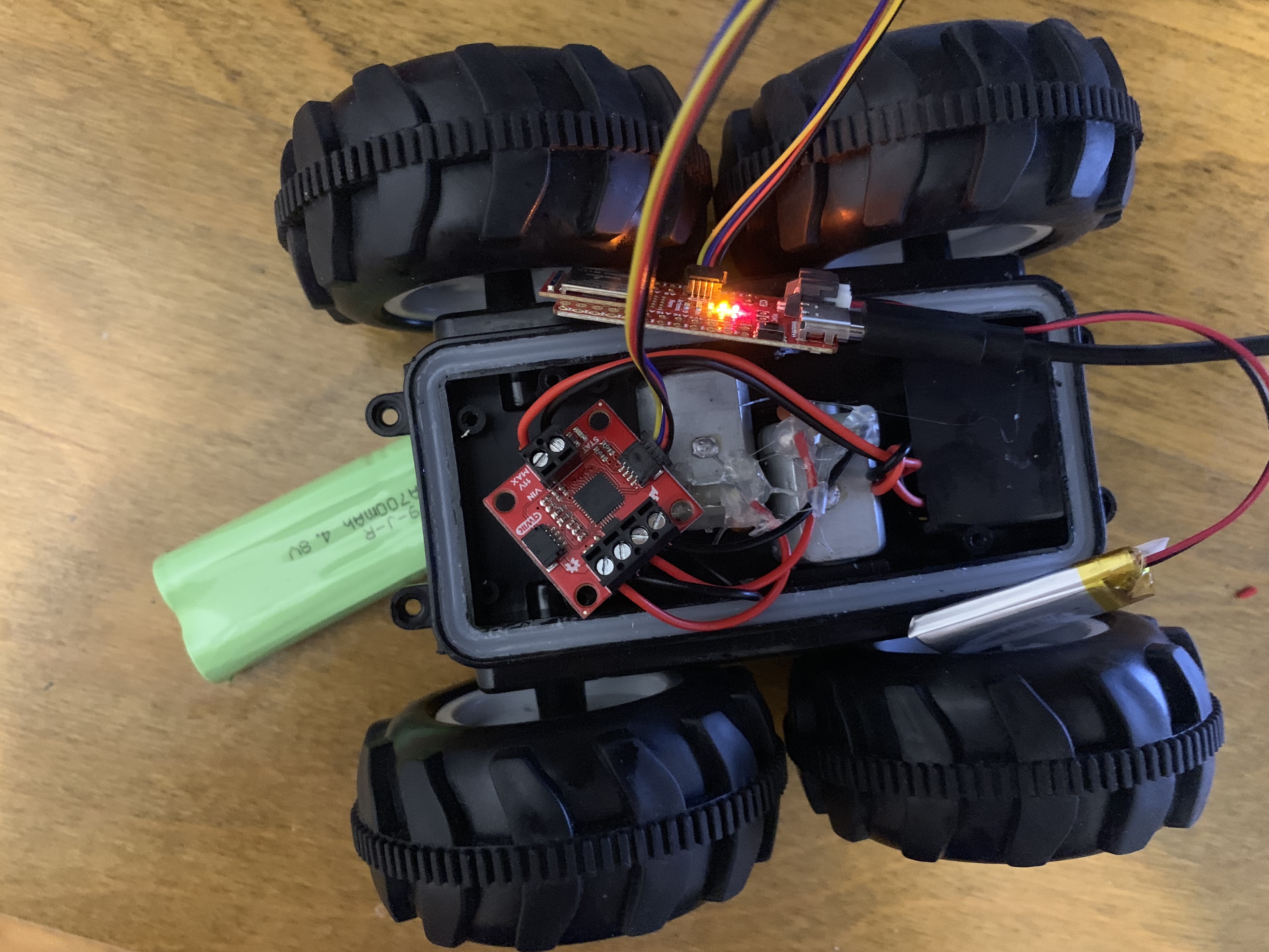
Figure 2: RC car with the Artemis board assembled.
Programming
Next, we will have to run an example code from the library (File->Examples->Wire-> Example1_wire) to find the I2C address of the SCMD board, so we could use it to modify our program. The I2C address of the board is “0x5D”, which is shown in Figure 3.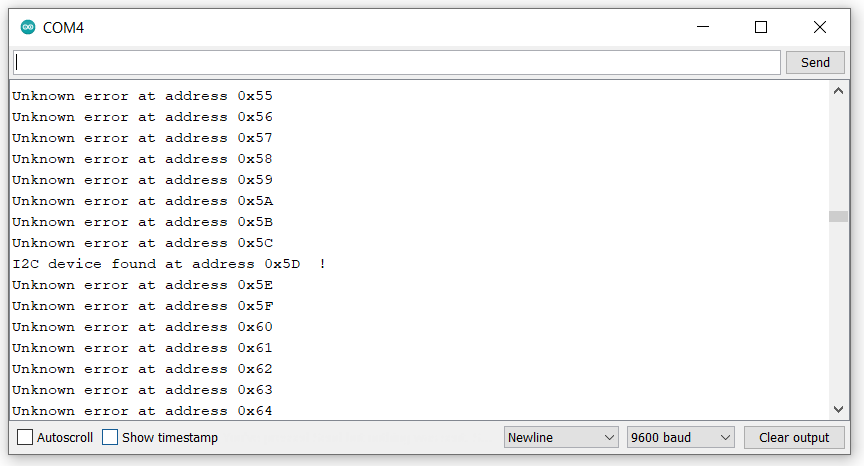
Figure 3: The I2C address of the SCMD board.
Then, we opened the motor test program from the example and modified the I2C address to the value 0x5D in order to work with our board. We realized that the program works properly, so we expanded the program to the two motors control and tested the value of the motor speed limit. From the reference, the motor level can be set from 0 to 255, but when we ran several tests, we observed that both motors do not spin at the same rate. The left motor can run at the level 30 to 255, and the right motor can run at the level 65 to 255. In Video 1, it shows that both motors run at their lowest level.Video 1: The motors operate at their lowest level.
Therefore, we will need to calibrate the motor level to make it move a fairly straight line. The number we used in the demonstration is 100 for the left motor and 125 for the right motor. We could see the robot can move a perfectly straight line in the slow-motion video. The code is shown in Figure 4.Video 2: Robot walks a straight line (normal mode) and (slow-motion mode).
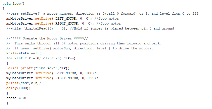
Figure 4: The code of going straight.
Robot Creativity Behavior
Later, we would like to control our robot by whistling and clapping. We combined the motor program with the microphone program in lab 1 in order to achieve this idea. We observed the frequency of the whistle is around 800Hz to 1500Hz, so we stop both motors under this condition. Besides, we operate the motor when the frequency is over 3000Hz. If the motors operate, it will determine whether the status is the forward mode or the turning mode. By default, the motor will operate in the forward mode, but when each time the whistle is triggered, the mode setting will change to the other mode. In Video 3, we could see that when the whistle is blown, the motor will move forward, and the next time the whistle sounds, only one side of the motor will turn. We could see the actual operation in Video 4 and the code is shown in Figure 5.Video 3: Motors demonstration while the program is running.
Video 4: The full demonstration of the robot.
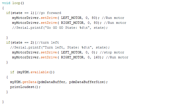

Figure 5: The code of controling robot by whistling.
Robot Creativity Behavior
Open loop control in the simulator
In this section, we will use the Jupyter notebook to control the robot in the simulator. We followed the instructions from the course website to download the base code in VM. Once the package is installed, we could open the simulator by entering “lab4 manager” in the terminal and open the Jupyter notebook in the other terminal. We will modify our program on the given python code to make the robot take a rectangular loop.Programming
The original idea is to use the odometry position to find the distance that the robot has moved and make the robot turned while the distance is reached to the given value. Then, the robot will turn until the difference between the turning point and the reaching point is over 1.5 rad because the 90 degrees is about 1.57 rad. The code is shown in Figure 6.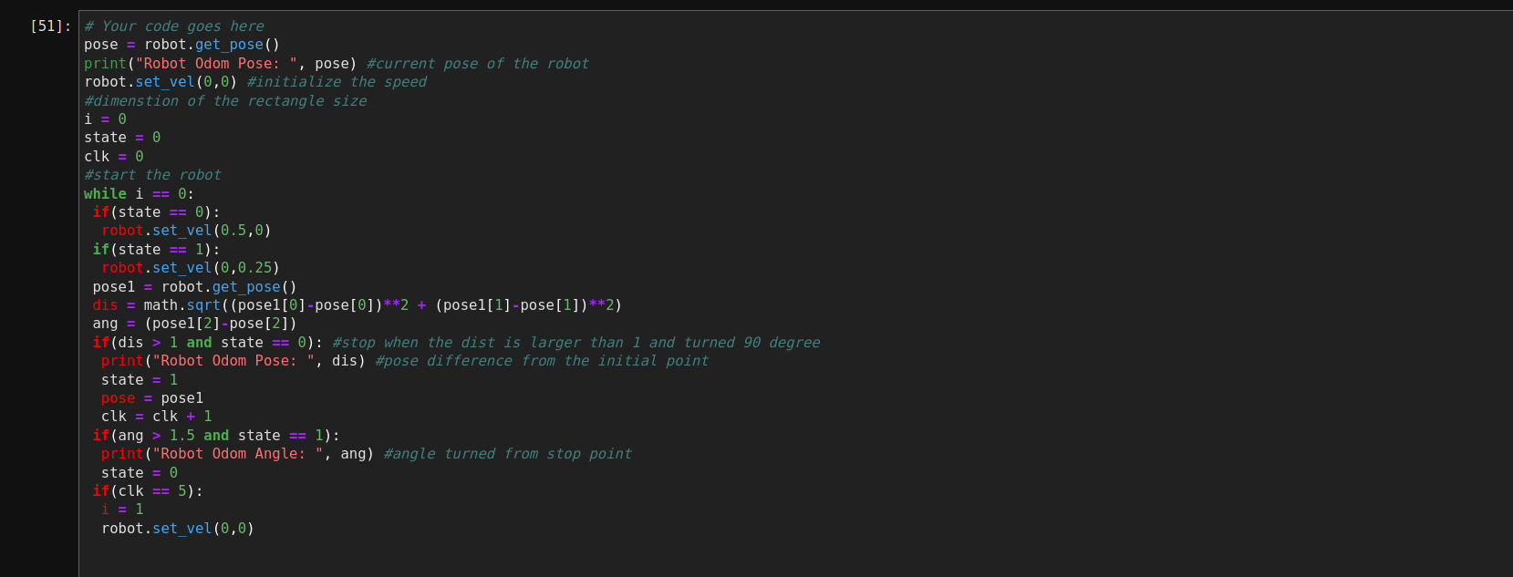
Figure 6: The loop control program with the position information.
Robot Creativity Behavior
However, we tested the program and the robot will sometimes freeze at a location, which is shown in Video 5. The reason is that there is a huge noise in the position function, so the value of the angle is always less than 1.57.Video 5: The robot stuck at a location.
To solve this problem, we decided not to use any position information to control the robot. We just need the dimensions of the rectangle size and the speed of the robot. We could calculate the delay time for the robot to move or turn. The code is shown in Figure 7.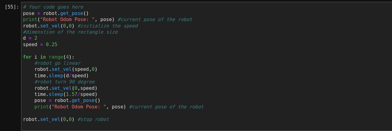
Figure 7: The loop control program with speed information.
In Video 6, we could see that the robot can move a rectangular shape in the simulator, but the odometry is not a perfect shape. We used Matlab to re-draw the robot path, which is shown in Figure 8. We could see that both tests have a delay while turning, so the angle is not close to 90 degrees. In order to solve this issue, we will need to use several sensors as feedback to ensure that the robot is moving at a right angle.Video 6: The demonstration of the rectangular loop.
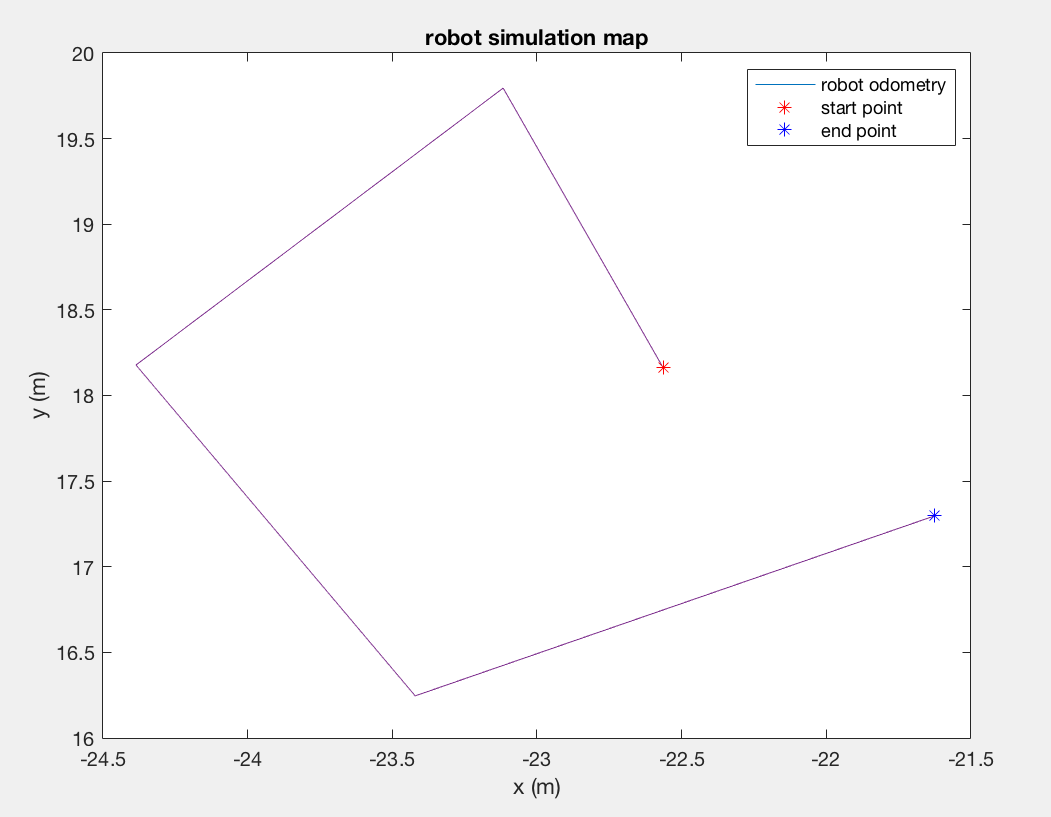
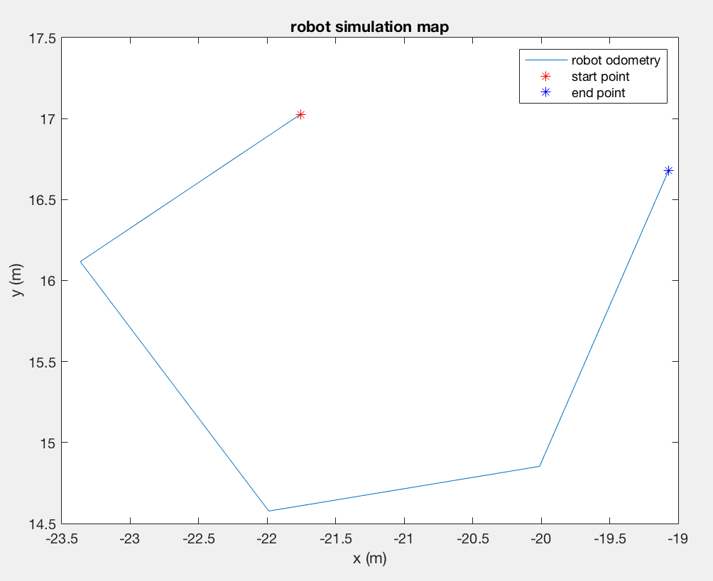
Figure 8: The robot paths generated by Matlab. Test 1 (right), Test 2 (left).